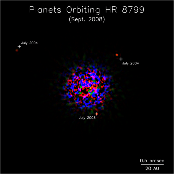
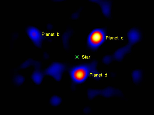
[/caption]
Using their backyard telescope, today? No; however, this image of three exoplanets required just 1.5 meters (diameter; 60 inches) of a telescope mirror, not vastly larger than the biggest backyard ‘scope.
These particular exoplanets orbit the star HR 8799, and have been imaged directly before, by one of the 10-meter (33-foot) Keck telescopes and the 8.0-meter (26-foot) Gemini North Observatory, both on Mauna Kea in Hawaii; they are among the first to be so imaged, as reported by Universe Today in November 2008 First Image of Another Multi-Planet Solar System.
So how did Gene Serabyn and colleagues manage the trick of taking the image above, using just a 1.5-meter-diameter (4.9-foot) portion of the famous Palomar 200-inch (5.1 meter) Hale telescope’s mirror?

They did it by working in the near infrared, and by combining two techniques – adaptive optics and a coronagraph – to minimize the glare from the star and reveal the dim glow of the much fainter planets.
“Our technique could be used on larger ground-based telescopes to image planets that are much closer to their stars, or it could be used on small space telescopes to find possible Earth-like worlds near bright stars,” said Gene Serabyn, who is an astrophysicist at JPL and visiting associate in physics at the California Institute of Technology in Pasadena.
The three planets, called HR8799b, c and d, are thought to be gas giants similar to Jupiter, but more massive. They orbit their host star at roughly 24, 38 and 68 times the distance between our Earth and the Sun, respectively (Jupiter resides at about five times the Earth-Sun distance). It’s possible that rocky worlds like Earth circle closer to the planets’ homestar, but with current technology, they would be impossible to see under the star’s glare.
The star HR 8799 is a bit more massive than our sun, and much younger, at about 60 million years, compared to our sun’s approximately 4.6 billion years. It is 120 light-years away in the constellation Pegasus. This star’s planetary system is still active, with bodies crashing together and kicking up dust, as recently detected by NASA’s Spitzer Space Telescope. Like a fresh-baked pie out of the oven, the planets are still warm from their formation and emit enough infrared radiation for telescopes to detect.
To take a picture of HR 8799’s planets, Serabyn and his colleagues first used a method called adaptive optics to reduce the amount of atmospheric blurring, or to take away the “twinkle” of the star. For these observations, technique was optimized by using only a small fraction of the telescope was used. Once the twinkle was removed, the light from the star itself was blocked using the team’s coronograph, an instrument that selectively masks out the star. A novel “vortex coronagraph,” invented by team member Dimitri Mawet of JPL, was used for this step. The final result was an image showing the light of three planets.
While adaptive optics is in use on only a few amateurs’ telescopes (and a relatively simple kind at that), the technology will likely become widely available to amateurs in the next few years. However, vortex coronagraphs may take a bit longer.
“The trick is to suppress the starlight without suppressing the planet light,” said Serabyn.
The technique can be used to image the space lying just a few arcseconds from a star. This is as close to the star as that achieved by Gemini and Keck – telescopes that are about five and seven times larger, respectively.
Keeping telescopes small is critical for space missions. “This is the kind of technology that could let us image other Earths,” said Wesley Traub, the chief scientist for NASA’s Exoplanet Exploration Program at JPL. “We are on our way toward getting a picture of another pale blue dot in space.”
Sources: JPL, Nature, Astrophysics Journal (preprint is arXiv:0912.2287)


If I knew back in grad school how cool it is to discover exoplanets, I would never go on to become a theoretical physicist 🙂
I wonder how this vortex coronagraph works. There is a PDF at http://www.opticsinfobase.org/oe/abstract.cfm?uri=oe-16-14-10200, but it is with a paid access. I know that the diffraction on the occulter can be reduced by specially shaped occulters, but thought that that’s not the only problem at ground based coronagraphs. I thought that an important part of the diffraction occurs already in the atmosphere (and also in the gas clouds surrounding the observed star, or on the way). I know that to bypass the atmospheric diffraction, space based occulters were suggested, so I wonder how the vortex occulter manages to handle it.
@ trux:
No paywall for me?!
“A schematic diagram of an optical vortex coronagraph is shown in Fig. 1. The primary star
(S1) is focused on the axis of an optical vortex lens (OVL) whereas the secondary star (S2) is
imaged at a separate point. Spatial filtering of S1 is achieved by placing an overfilled
aperture, i.e., a Lyot stop (LS), in the plane of the exit pupil of the system. Light from this onaxis
star is, in principle, completely diffracted outside the exit pupil, whereas off-axis light
sources may uniformly fill the exit pupil. The Lyot stop therefore transmits to the imaging
camera (Cam2) only light from S2.
In practice the moving inhomogeneous atmosphere (Atm)
severely distorts the wavefronts at the entrance pupil (or aperture, Ap) of the telescope; hence,
an ideal stationary image of S1 does not form at the axis of the OVL. Fortunately, the
wavefront at the entrance pupil predominantly suffers only tip-tilt distortion when the radius
of the entrance pupil, Rap, is less than the Fried parameter, r0 ~ 100 mm. Furthermore,
atmospheric fluctuations giving rise to tip-tilt distortion occur on the order of Tatm ~ 0.01 sec
[23]. Using an optical detector and a feed-back system with a response time ? << Tatm, one
may construct an adaptive optics system that achieves near-perfect seeing when Rap < r0 [23].
We employed a tip-tiled corrector to stabilize the imaged star system on the optical vortex
lens. This was accomplished by forming an image of the entrance pupil on a piezoelectrically
driven tip-tilt mirror (TTM). The wavefront was corrected by means of a high speed camera
(Cam1) [Andor iXon EMCCD] and a feedback signal from the camera to TTM [LabView
software]. A Pellicle beamsplitter reflects roughly half of the beam to the high speed imaging
camera and the remainder is transmitted to a long exposure telescope camera [SBIG ST-
402ME]. To ensure that the aperture Ap forms the required image at the lens L2 (the entrance
of the coronagraph system) we found it necessary to insert an optical relay comprised of
lenses RL1 and RL2."
[Citation
Grover A. Swartzlander, Jr., Erin L. Ford, Rukiah S. Abdul-Malik, Laird M. Close, Mary A. Peters, David M. Palacios, and Daniel W. Wilson, "Astronomical demonstration of an optical vortex coronagraph," Opt. Express 16, 10200-10207 (2008) ]
Piezoelectrics, what would we do without them?
Funny, indeed, I can access the PDF now too. When I found it first, it asked me to pay.
trux,
The last of my sources is a paper titled “The Vector Vortex Coronagraph: Laboratory Results and First Light at Palomar Observatory”. I also have a link to the arXiv preprint. This paper describes how a vector vortex coronagraph works, and has plenty of references to other papers, where more details can be found.
Great, thanks! I did not try that link first. Looks good. I am going to read it.
Well, I do not know the details yet, but basically unlike the adaptive optics which seems to be a pretty complex and expensive device for amateurs, the vortex coronagraph should be technologically simpler (I mean alone without the adaptive optics). Hence I see no reason why amateurs should necessarily wait much longer to get it too as you write in the article.
BTW, you wrote there are already some amateur telescopes with adaptive optics – it would be nice to have an article about them. Do they use a laser beam to create a reference point in the upper atmosphere, or do they calibrate on some nearby star? Isn’t use of such strong laser beams regulated? What power is needed? Well, there are many questions I’d love to see addressed in such an article, so if you have access to the information, the article would be certainly appreciated by many!
@ Jean Tate,
At the eighth paragraph, third & fourth lines:
Err… looks like you messed up the “copy & paste” job there; the article source actually reads: ” This technique was optimized by using only a small piece of the telescope.”
Also, at the first paragraph, in the first line, there should be a comma after the term “however”, to mean: nevertheless; on the other hand; in spite of that. Whereas “however” without a comma after it means: to whatever extent or degree.
I’ll get my coat and see myself out…
Thanks trux. I’ll add that idea to my (rather long, sorry) list of articles to research.
Thanks IVAN3MAN_AT_LARGE; fixed.