Air Force X-37B Spaceplane Launches on May 20 with Military, NASA and LightSail Payloads: Watch Live

Fourth flight of the X-37B Orbital Test Vehicle is set for blastoff on May 20, 2015 from Cape Canaveral, Florida Photo: Boeing

Fourth flight of the secretive U.S. Air Force X-37B Orbital Test Vehicle is set for blastoff on May 20, 2015 from Cape Canaveral, Florida. Photo: Boeing
Story updated with further details and photos[/caption]

All systems are currently “GO” for the fourth launch of the US Air Force’s secretive unmanned, X-37B military space plane this Wednesday, May 20, on a flight combining both US national security experimental payloads as well as civilian science experiments sponsored by NASA, US Universities, commercial companies, and the solar sailing LightSail test from the Planetary Society.

LightSail marks the first controlled, Earth orbit solar sail flight according to the non-profit Planetary Society. It will launch as a separate cubesat experiment. NASA also has an advanced materials science experiment flying aboard the robotically controlled X-37B.

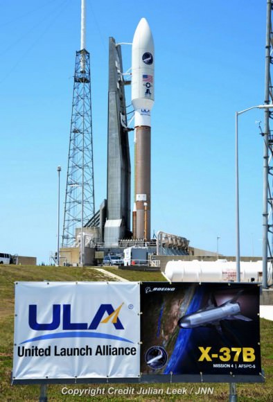
The X-37B is set for blastoff atop a two stage United Launch Alliance (ULA) Atlas V 501 rocket on the AFSPC-5 mission under contract for the U.S. Air Force Rapid Capabilities Office.

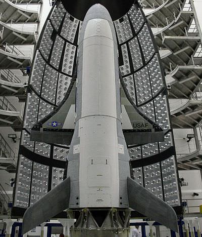
The Boeing-built X-37B is an unmanned reusable mini shuttle, also known as the Orbital Test Vehicle (OTV) and is flying on the OTV-4 mission. It launches vertically like a satellite but lands horizontally like an airplane.

Although virtually all the goals of the X-37B program are shrouded in secrecy, some details on the national security objectives have emerged and there are several unclassified experiments flying along as secondary objectives on the rocket and space plane, among them are experiments for NASA and the Planetary Society.

LightSail launches aboard the X-37B on May 20, 2015.  Credit: The Planetary Society
LightSail launches aboard the X-37B on May 20, 2015. Credit: The Planetary Society

Among the primary mission goals of the first three flights were check outs of the vehicles capabilities and reentry systems and testing the ability to send experiments to space and return them safely. OTV-4 will shift somewhat more to conducting research.

“We are excited about our fourth X-37B mission,” Randy Walden, director of the USAF’s Rapid Capabilities Office, said in a statement. “With the demonstrated success of the first three missions, we’re able to shift our focus from initial checkouts of the vehicle to testing of experimental payloads.”

Liftoff will take place from Space Launch Complex (SLC)-41 at Cape Canaveral Air Force Station, Florida, at some point during a four hour launch period that opens at 10:45 a.m. EDT and extends until 2:45 p.m. EDT on May 20.

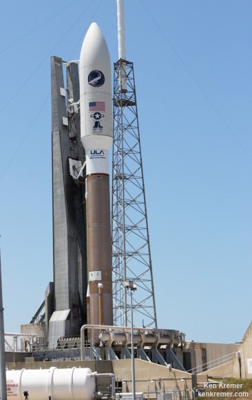
ULA announced that the Launch Readiness Review was completed on Monday and everything is progressing normally toward the AFSPC-5 launch. The rocket is fully assembled and the space plane is encapsulated inside the 5 meter diameter payload fairing. It rolled out to the pad today, Tuesday, May 19.

You can watch the Atlas launch live via a ULA webcast here: http://www.ulalaunch.com

The ULA webcast begins at 10:45 a.m. EDT on May 20. The precise launch time is classified and won’t be announced until Wednesday morning.

The weather prognosis has improved markedly to a 60 percent chance of favorable weather conditions, up from only a 40 percent chance this past weekend.

The primary weather concerns are for violations of the launch weather rules related to cumulus clouds, surface electric fields, anvil clouds and lightning.

Launch officials are hopeful that acceptable launch conditions will occur sometime during the lengthy four hour launch window.

In the event of a 24 hour delay due to weather or technical issues, the outlook drops to only a 30% chance of favorable weather conditions during the launch window.

The OTV is somewhat like a miniature version of NASA’s space shuttles. Boeing has built two OTV vehicles.
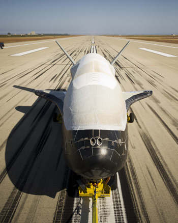
2nd X-37B Orbital Test Vehicle Successfully Completes 1st Flight by landing at Vandenberg AFB, Calif., on June 16, 2012.  The record setting mission lasted 469 days in earth orbit.  Designed to be launched like a satellite and land like an airplane, the second X-37B Orbital Test Vehicle, built by Boeing for the United States Air Force’s Rapid Capabilities Office, is an affordable, reusable space vehicle. Credit: Boeing. See landing video below
2nd X-37B Orbital Test Vehicle Successfully Completes 1st Flight by landing at Vandernberg AFB, Calif., on June 16, 2012. It is designed to be launched like a satellite and land like an airplane. Credit: Boeing.

Altogether the two X-37B vehicles have spent a cumulative total of 1367 days in space during the first three OTV missions and successfully checked out the vehicles reusable flight, reentry and landing technologies.

The reusable space plane is designed to be launched like a satellite and land on a runway like an airplane and a NASA space shuttle. The X-37B is one of the newest and most advanced reentry spacecraft.

The 11,000 pound (4990 kg) state-of -the art reusable OTV space plane was built by Boeing and is about a quarter the size of a NASA space shuttle. It was originally developed by NASA but was transferred to the Defense Advanced Research Projects Agency (DARPA) in 2004.

All three OTV missions to date have launched from Cape Canaveral, Florida and landed at Vandenberg Air Force Base, California. Future missions could potentially land at the shuttle landing facility at the Kennedy Space Center, Florida.

The first OTV mission launched on April 22, 2010, and concluded on Dec. 3, 2010, after 224 days in orbit.
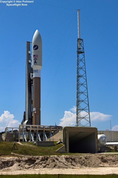
USAF X-37B orbital test vehicle poised for launch atop  United Launch Alliance Atlas V rocket on May 20, 2015 on OTV-4 mission. Credit: Alex Polimeni
USAF X-37B orbital test vehicle poised for launch atop United Launch Alliance Atlas V rocket on May 20, 2015 on OTV-4 mission. Credit: Alex Polimeni

The following flights were progressively longer in duration. The second OTV mission began March 5, 2011, and concluded on June 16, 2012, after 468 days on orbit. The third OTV mission launched on Dec. 11, 2012 and landed on Oct. 17, 2014 after 674 days in orbit.

The vehicle measures 29 ft 3 in (8.9 m) in length with a wingspan of 14 ft 11 in (4.5 m). The payload bay measures 7 ft × 4 ft (2.1 m × 1.2 m). The space plane is powered by Gallium Arsenide Solar Cells with Lithium-Ion batteries.

The OTV-4 mission will shift its focus at least somewhat from tests of the vehicles performance to more on science experiments both with extra capacity available on the Atlas V rocket and payload space aboard the X-37B itself.

“We’re very pleased with the experiments lined-up for our fourth OTV Mission OTV-4,” Walden noted.

“We’ll continue to evaluate improvements to the space vehicle’s performance, but we’re honored to host these collaborative experiments that will help advance the state-of-the-art for space technology

Among the experiments for the flight are 10 CubeSats. They will launch in the Aft Bulkhead Carrier (ABC) located below the Centaur upper stage that contains eight P-Pods to release the CubeSats.

Following primary spacecraft separation the Centaur will change altitude and inclination in order to release the CubeSat spacecraft, ULA said in a statement.

They are sponsored by the National Reconnaissance Office (NRO) and NASA and were developed by the U.S. Naval Academy, the Aerospace Corporation, the Air Force Research Laboratory, California Polytechnic State University, and Planetary Society.

NASA is also flying an advanced materials science payload on the X-37B called the Materials Exposure and Technology Innovation in Space (METIS) investigation that will build on more than a decades worth of materials science research on the International Space Station (ISS) research.

“By flying the Materials Exposure and Technology Innovation in Space (METIS) investigation on the X-37B, materials scientists have the opportunity to expose almost 100 different materials samples to the space environment for more than 200 days. METIS is building on data acquired during the Materials on International Space Station Experiment (MISSE), which flew more than 4,000 samples in space from 2001 to 2013, NASA said in a statement.

“By exposing materials to space and returning the samples to Earth, we gain valuable data about how the materials hold up in the environment in which they will have to operate,” said Miria Finckenor, the co-investigator on the MISSE experiment and principal investigator for METIS at NASA’s Marshall Space Flight Center in Huntsville, Alabama.

“Spacecraft designers can use this information to choose the best material for specific applications, such as thermal protection or antennas or any other space hardware.”

Stay tuned here for Ken’s continuing Earth and Planetary science and human spaceflight news.
Ken Kremer

United Launch Alliance to launch USAF X-37B orbital test vehicle on May 20, 2015. Credit: Julian Leek
US Air Force X-37B OTV-4 mini space shuttle is encapsulated in 5 meter payload fairing and bolted atop an Atlas 5 rocket at Pad 41 at Cape Canaveral Air Force Station, Florida prior to planned 20 May 2015 launch. This up close view of the nose cone holding the secretive  X-37B shows the umbilical line attachments. Credit: Ken Kremer
US Air Force X-37B OTV-4 mini space shuttle is encapsulated in 5 meter payload fairing and bolted atop an Atlas 5 rocket at Pad 41 at Cape Canaveral Air Force Station, Florida prior to planned 20 May 2015 launch. Credit: Ken Kremer/kenkremer.com
The X-37B is similar in many ways to NASA's space shuttle - but it is far smaller and unmanned. Photo Credit: Air Force
The X-37B is similar in many ways to NASA’s space shuttle – but it is far smaller and unmanned. Photo Credit: Air Force
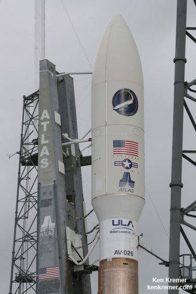
US Air Force X-37B OTV-2 mini space shuttle is encapsulated in 5 meter payload fairing and bolted atop an Atlas 5 rocket at Pad 41 at Cape Canaveral Air Force Station, Florida prior to 5 March 2011 launch. This up close view of the nose cone holding the secretive  X 37-B shows the umbilical line attachments. Credit: Ken Kremer
US Air Force X-37B OTV-2 mini space shuttle is encapsulated in 5 meter payload fairing and bolted atop an Atlas 5 rocket at Pad 41 at Cape Canaveral Air Force Station, Florida prior to 5 March 2011 launch. This up close view of the nose cone holding the secretive X 37-B shows the umbilical line attachments. Credit: Ken Kremer/kenkremer.com

2nd Launch Disaster in 3 Weeks Strikes Russia, Destroying Proton Rocket and Mexican Comsat

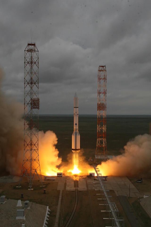
Russian Proton rocket blasts off at 11:47 a.m. local time (1:47 a.m. EDT) from the Baikonur Cosmodrome in Kazakhstan but ended in disaster about eight minutes later with destruction of the rocket and Mexican satellite payload heading to orbit Credit: Roscosmos

Russian Proton rocket blasts off at 11:47 a.m. local time (1:47 a.m. EDT) from the Baikonur Cosmodrome in Kazakhstan but ended in disaster about eight minutes later with destruction of the rocket and Mexican comsat satellite payload heading to orbit. Credit: Roscosmos
Story updated with additional details [/caption]

For the second time in less than three weeks, a major disaster struck the Russian space program when the launch of a Proton-M rocket ended in catastrophic failure about eight minutes after today’s (May 16) liftoff from the Baikonur Cosmodrome in Kazakhstan, resulting in the complete destruction of the Mexican communications satellite payload.

The Proton-M rocket initially lifted off successfully at 11:47 a.m. local time (1:47 a.m. EDT, 547 GMT) from the Baikonur Cosmodrome in Kazakhstan, but soon experienced an “emergency situation at 497 seconds into the flight,” according to a brief official statement released by Roscosmos, the Russian Federal Space Agency today, after the mishap.

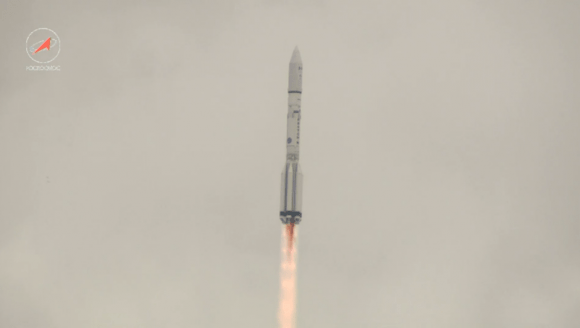
The launch catastrophe was caused by a failure in the rockets Breeze-M third stage, says Roscosmos. It took place during a live broadcast from the agency’s website. A video shows the rocket disappearing into cloudy skies shortly after liftoff.

The failure comes just one week after the spinning, out-of-control Russian Progress 59 cargo freighter bound for the ISS met its undesired early demise when it fell uncontrolled from orbit last Friday, May 8, following its botched April 28 launch on a Russian Soyuz-2.1A carrier rocket, also from Baikonur – as reported by Universe Today – here, here, and here.

The Proton-M carrier rocket was lofting the Mexsat 1 communications satellite, also known as Centenario, under a contract with the Mexican government.

“The failure happened on the 497th second of the flight, at an altitude of 161 kilometers [100 miles]. The third stage, the booster vehicle and the spacecraft almost completely burned up in the atmosphere. As of now there are no reports of debris reaching the ground,” the agency said in a statement.

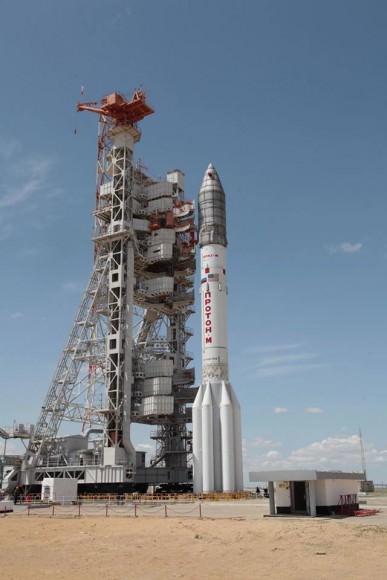
Prelaunch view of Russian Proton rocket poised at launch pad at the Baikonur Cosmodrome in Kazakhstan.   Credit: Roscosmos
Prelaunch view of Russian Proton rocket poised at launch pad at the Baikonur Cosmodrome in Kazakhstan. Credit: Roscosmos

The Breeze-M third stage was to loft Mexsat 1 to its destination in geostationary orbit over 22,000 miles above Earth at 113 degrees west longitude.

The 58.2 m (191 ft) tall Proton rocket is built and operated by Khrunichev State Research and Production Space Center and marketed by International Launch Services (ILS).

After reaching an altitude of about 161 km (100 mi) the rocket and Mexsat 1 payload fell back to Earth and burned up over the Chita region of Russia, which is located south west of the Siberian Baikal region, said the Russian News agency TASS.

“The rocket and its payload, a Mexican communication satellite, burned up in the atmosphere,” according to a report by Sputnik International, a Russian News agency.

At this time, local residents have not reported or claimed anything regarding possible debris and there is no information about casualties or destruction, TASS noted.

Mi8 helicopters from Russia’s Emergencies Ministry have been dispatched to the area to look for any debris.

The 5.4 ton Mexsat 1 communication satellite was built by Boeing Satellite Systems International for the Mexican government’s Ministry of Communications and Transportation, the Secretaria de Comunicaciones y Transportes (SCT).

Russian Proton rocket in flight after blast off at 11:47 a.m. local time (1:47 a.m. EDT) from the Baikonur Cosmodrome in Kazakhstan. It ended in disaster about eight minutes later with destruction of the rocket and Mexican satellite payload heading to orbit.  Credit: Roscosmos
Russian Proton rocket in flight after blast off at 11:47 a.m. local time (1:47 a.m. EDT) from the Baikonur Cosmodrome in Kazakhstan. It ended in disaster about eight minutes later with destruction of the rocket and Mexican satellite payload heading to orbit. Credit: Roscosmos

The Breeze-M failure occurred about 1 minute prior to separation of the third stage from Mexsat 1.

“The emergency situation happened at 08:56 Moscow time, one minute to the scheduled separation of the Breeze-M booster and the Mexican MexSat-1 space apparatus,” TASS reported.

A malfunction with the third stage steering engine may be the cause of the doomed flight.

“A preliminary reason of the accident with Proton is a failure of the steering engines of the third stage,” sources told TASS.

“The analysis of the telemetry allows for supposing that there was a failure in one of the third stage’s steering engines. This is now considered as one of the main reasons.”

Exactly one year ago, another Proton rocket crashed at a similar point when the third stage engines failed during the Proton launch of Russia’s advanced Express-AM4R satellite.

“Khrunichev and International Launch Services (ILS) regret to announce an anomaly during today’s Proton mission,” ILS said in a statement issued after the launch failure.

ILS said an accident investigation board has been appointed to determine the cause of the failure and recommend corrective actions.

“A Russian State Commission has begun the process of determining the reasons for the anomaly. ILS will release details when data becomes available,” said ILS.

They hope to return the workhorse Proton to flight as soon as possible.

“ILS remains committed to providing reliable, timely launch services for all its customers. To this end, ILS will work diligently with its partner Khrunichev to return Proton to flight as soon as possible.”

This was the eleventh failure of the Proton-M rocket or Breeze-M upper stage in 116 launches since the inaugural liftoff in April 2001.

Mexsat 1 had a planned lifetime of 15 years. It was to provide mobile satellite services to support national security, civil and humanitarian efforts and will provide disaster relief, emergency services, telemedicine, rural education, and government agency operations.

Media reports indicate it was insured for about $390 million.

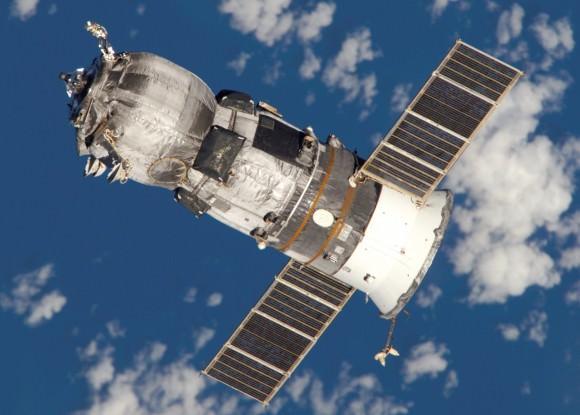
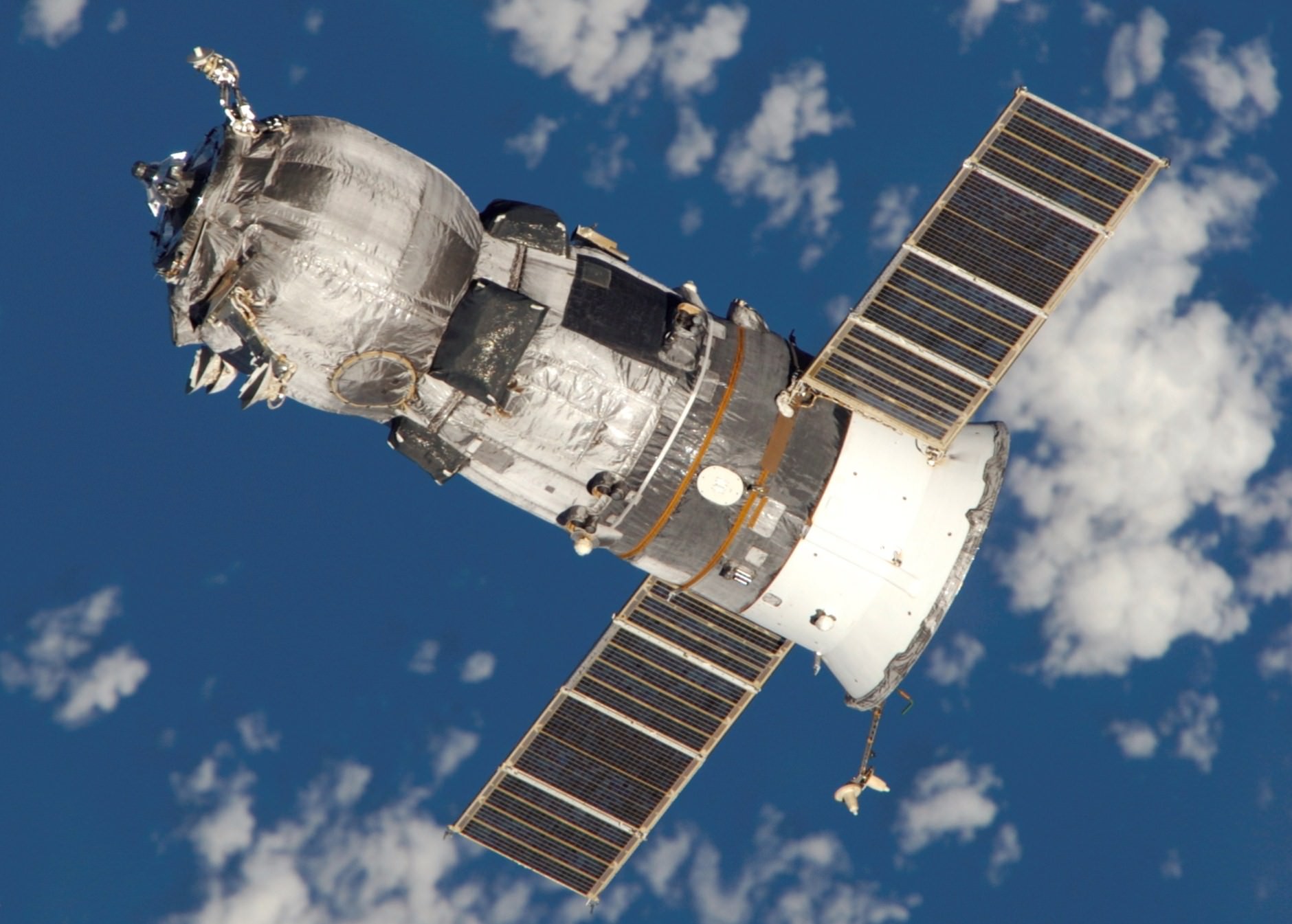
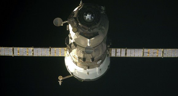
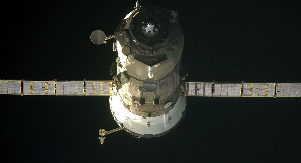
File photo of a Russian Progress cargo freighter. Credit: Roscosmos

Stay tuned here for Ken’s continuing Earth and planetary science and human spaceflight news.
Ken Kremer

Wayward Progress Destroyed During Fiery Plummet, ISS Crew Launches ‘Under Evaluation’

File photo of a Russian Progress cargo freighter. Credit: Roscosmos

File photo of a Russian Progress cargo freighter. Credit: Roscosmos
Story updated with further details[/caption]

The spinning, out-of-control Russian Progress 59 cargo freighter met its undesired early demise when it fell from orbit early Friday, May 8, and was destroyed during the unplanned fiery plummet through the Earth’s atmosphere.

As a result of the loss of the unmanned Progress 59 spacecraft, which was bound for the International Space Station (ISS) on a routine resupply mission, the timelines of upcoming crew rotations and new launches are “under evaluation” – Universe Today learned according to Russian and American space sources.

The doomed Progress freighter “ceased to exist” after it reentered the Earth’s atmosphere 05.04 Moscow time on May 8, 2015 (10:04 p.m. EDT May 7) over the central Pacific Ocean,” according to an official statement from Roscosmos, the Russian Space Agency.

The consequences of the failure might cause “postponements of upcoming station crew changes to June” and blastoffs “to July” according to Russian space industry and media sources.

The vessel, also known as Progress M-27M, burned up minutes later and any surviving pieces fell over the Pacific Ocean.

“Debris fell about 900 kilometers west of the Marquesas Islands in the central Pacific Ocean,” a space industry source told the Russian news agency TASS.

“Roscosmos plans to adjust the program of flights to the International Space Station (ISS) due to the recent accident involving the Progress M-27M spacecraft,” according to the TASS rocket and space industry source.

Roscosmos quickly established an investigation board to determine the cause of the Progress failure and any commonalities it might have with manned launches of the Soyuz rocket and capsule, and report back by 13 May.

“The results of investigation of the incident related to “Progress M-27M” will be presented no later than 13 May following the completion of the state commission,” Roscosmos stated.

Russian mission controllers lost control of the Progress 59 spacecraft shortly after its otherwise successful launch to the ISS on April 28 from the Baikonur space center in Kazakhstan atop a Soyuz-2.1A carrier rocket.

Soon after detaching from the rockets third stage, it began to spin out of control at about 1.8 times per second, as seen in a video transmitted from the doomed ship.

After control could not be reestablished, all hope of docking with the ISS was abandoned by Roscosmos.

NASA officials said that the current ISS Expedition 43 six person crew is in no danger. The station has sufficient supplies to last until at least September, even if no other supplies arrive in the meantime.

“The spacecraft was not carrying any supplies critical for the United States Operating Segment (USOS) of the station, and the break up and reenty of the Progress posed no threat to the ISS crew,” NASA said in a statement.

“Both the Russian and USOS segments of the station continue to operate normally and are adequately supplied well beyond the next planned resupply flight.”

There is a stock of propellants onboard in the Russian segment that can be used for periodically required station reboosts.

According to TASS, “the cause of the accident with the Russian Progress M-27M spacecraft has not been established yet, Russian Deputy Prime Minister Dmitry Rogozin told journalists on Friday.”

“Not yet,” he said, answering a question on whether causes of the accident had been established.

File photo of a Russian Progress cargo freighter. Credit: Roscosmos

Because the cause of Progress failure is not yet clear, the schedules for upcoming crew departures and launches to the ISS via Russian Soyuz rockets and capsules are “under evaluation,” according to sources.

There is a significant potential for a delay in the planned May 13 return to Earth of the three person crew international crew consisting of NASA astronaut and current station commander Terry Virts and flight engineers Samantha Cristoforetti of ESA (European Space Agency) and Anton Shkaplerov of Roscosmos, who have been aboard the complex since November 2014.

They comprise the current Expedition 43 crew, along with the recently arrived crew of NASA astronaut Scott Kelly and Russian cosmonauts Mikhail Kornienko and Gennady Padalka who launched onboard a Soyuz capsule on March 27.

Kelly and Kornienko comprise the first ever “1 Year ISS Crew.”

Virts and his crewmates were due to head back to Earth in their Soyuz capsule on May 13. According to Russian sources, their return trip may be postponed to about June 11 to 13.

“The return from orbit of the expedition which is currently there is suggested to be postponed from May 14 to June,” said a TASS source.

Their three person replacement crew on Expedition 44 were due to blastoff on the next planned manned Soyuz launch on May 26 from the Baikonur Cosmodrome in Kazakhstan. This launch may now be delayed as well, to mid or late July.

“More time will be needed to check already manufactured rockets,” said a source. “A manned Soyuz launch may be made in the last ten days of July.”

“The proposal was forwarded by a Roscosmos working group and has not been approved yet,” reports TASS.

An official announcement by Roscosmos of any ISS schedule changes may come next week since the scheduled return of Virts crew is only days away.

Another potential change is that the launch of the next unmanned Progress 60 (M-28M), could potentially be moved up from August to July, hinging on the outcome of the state commission investigation.

To date flights of the Progress vehicle have been highly reliable. The last failure occurred in 2011, shortly after the retirement of NASA’s Space Shuttle orbiters in July 2011. The loss of the Progress did cascade into a subsequent crew launch delay later in 2011.

"There's coffee in that nebula"... ehm, I mean... in that #Dragon.  Engineer Samantha Cristoforetti of the European Space Agency in Star Trek uniform as Dragon arrives at the International Space Station on April 17, 2015. Credit: NASA
“There’s coffee in that nebula”… ehm, I mean… in that #Dragon. Engineer Samantha Cristoforetti of the European Space Agency in Star Trek uniform as Dragon arrives at the International Space Station on April 17, 2015. Credit: NASA

The 7 ton Progress vehicle was loaded with 2.5 tons of supplies for the ISS and the six person Expedition 43 crew. Items included personal mail for the crew, scientific equipment, food, water, oxygen, gear and replaceable parts for the station’s life support systems.

The next SpaceX Falcon 9 launch carrying the CRS-7 Dragon cargo ship on a resupply mission for NASA to the ISS is slated for mid-June. The most recent SpaceX Dragon was launched on the CRS-6 mission on April 14, 2015.

At this time the SpaceX CRS-7 launch remains targeted for liftoff on June 19, 2015.

Stay tuned here for Ken’s continuing Earth and planetary science and human spaceflight news.
Ken Kremer

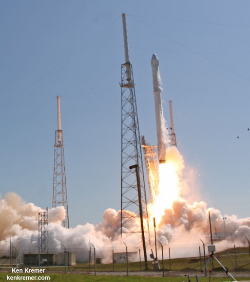
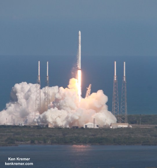
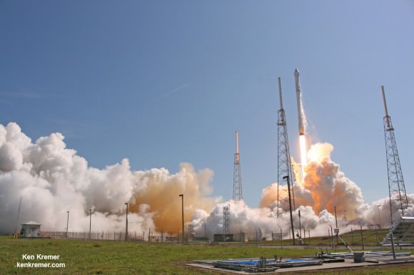
SpaceX Falcon 9 and Dragon blastoff from Space Launch Complex 40 at Cape Canaveral Air Force Station in Florida on April 14, 2015 at 4:10 p.m. EDT  on the CRS-6 mission to the International Space Station. Credit: Ken Kremer/kenkremer.com
SpaceX Falcon 9 and Dragon blastoff from Space Launch Complex 40 at Cape Canaveral Air Force Station in Florida on April 14, 2015 at 4:10 p.m. EDT on the CRS-6 mission to the International Space Station. Credit: Ken Kremer/kenkremer.com

Russia’s Out of Control Progress Freighter Doomed to Fiery Finale Friday

File photo of a Russian Progress cargo freighter. Credit: Roscosmos

Russia’s out-of-control Progress 59 cargo freighter is doomed to a fiery finale overnight Friday, May 8, according to Roscosmos, the Russian Space Agency.

The errant spaceship is expected to fall back to Earth and reenter the atmosphere early in the morning Moscow time following the latest orbital analysis by Roscosmos.

“The time window for the failed Progress spacecraft reentry in the Earth’s atmosphere was changed to a span between 01.13 a.m. and 04.51 a.m. Moscow time on May 8, according to Russia’s space agency Roscosmos,” according to the latest update today, May 7, from the Russian Sputnik news outlet.

According to a Roscosmos source, the unmanned Progress 59, also known as M-27M , would most likely make the atmospheric reentry over the Indian Ocean.

Roscosmos said in a statement that Progress 59 “will cease to exist” on Friday.

Most of the debris is expected to burn up. But any remaining fragments are likely to hit north of Madagascar.

Russian mission controllers lost control of the Progress 59 spacecraft ship – bound for the International Space Station (ISS) on a routine resupply mission – shortly after its otherwise successful launch on April 28 from the Baikonur space center in Kazakhstan atop a Soyuz-2.1A carrier rocket.

Soon after detaching from the rockets third stage, it began to spin out of control at about 1.8 times per second, as seen in a video transmitted from the doomed ship.

After control could not be reestablished, all hope of docking with the ISS was abandoned by Roscosmos.

Here’s a short video taken by the spinning Progress with NASA commentary:

The 7 ton vehicle was loaded with 2.5 tons of supplies for the ISS and the six person Expedition 43 crew. Items included personal mail for the crew, scientific equipment, as well as replaceable parts for the station’s life support systems and a stockpile of water and oxygen, according to Russia Today.

The Progress spacecraft is also loaded with a significant amount of fuel as it orbits Earth at an inclination of 51.6 degrees to the equator. This carries it over most of the populated world between 51.6 degrees north and south latitudes. But most of the area is over unpopulated oceans, making the chances of danger from falling debris very small.

The latest ground track reentry prediction for the Progress 59 (M-27M)  spacecraft showing orbital path around Earth as of May 7, 2015. Note: subject to change.  Credit: Aerospace Corp.
The latest ground track reentry prediction for the Progress 59 (M-27M) spacecraft showing orbital path around Earth as of May 7, 2015. Note: subject to change. Credit: Aerospace Corp.

To date the Progress vehicle have been highly reliable. The last failure occurred in 2011, shortly after the retirement of NASA’s Space Shuttle orbiters in July 2011.

Roscosmos has established an investigation board to determine the cause of the Progress failure and any commonalities it might have with manned launches of the Soyuz rocket and capsule.

“The conclusions are to be made by May 13, 2015,” according to a Roscosmos statement.

The potential exists for a delay in the next planned manned Soyuz launch with a three person international crew later on May 26 from the Baikonur Cosmodrome in Kazakhstan.

The ISS crew is in no danger and has sufficient supplies to last until at least September.

Besides the Russian Progress cargo ship, the ISS is resupplied by the commercial US SpaceX Dragon and Orbital Sciences Cygnus vessels and the Japanese HTV. ESA’s ATV has been retired after 5 flights.

The next Falcon 9 launch carrying the CRS-7 Dragon cargo ship on a resupply mission for NASA to the ISS is slated for mid-June. The most recent Dragon was launched on the CRS-6 mission on April 14, 2015.

SpaceX Falcon 9 and Dragon blastoff from Space Launch Complex 40 at Cape Canaveral Air Force Station in Florida on April 14, 2015 at 4:10 p.m. EDT  on the CRS-6 mission to the International Space Station. Credit: Ken Kremer/kenkremer.com
SpaceX Falcon 9 and Dragon blastoff from Space Launch Complex 40 at Cape Canaveral Air Force Station in Florida on April 14, 2015 at 4:10 p.m. EDT on the CRS-6 mission to the International Space Station. Credit: Ken Kremer/kenkremer.com

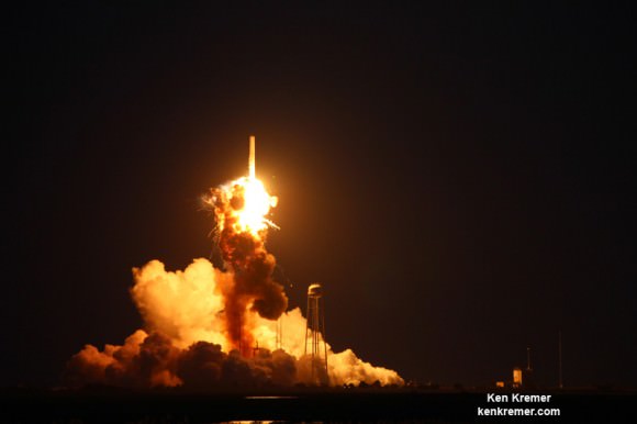
The last Orbital Sciences launch of an Antares rocket with the Orb-3 Cygnus resupply ship ended in a catastrophic explosion just seconds after liftoff on October 28, 2014.

The ISS lifeline hangs by a delicate thread.

Stay tuned here for Ken’s continuing Earth and planetary science and human spaceflight news.
Ken Kremer

Base of Orbital Sciences Antares rocket explodes moments after blastoff from NASA’s Wallops Flight Facility, VA, on Oct. 28, 2014, at 6:22 p.m. Credit: Ken Kremer – kenkremer.com

Key Facts and Timeline for SpaceX Crewed Dragon’s First Test Flight May 6 – Watch Live

SpaceX Pad Abort Test vehicle poised for May 6, 2015 test flight from SpaceX’s Space Launch Complex 40 (SLC-40) in Cape Canaveral, Florida. Credit: SpaceX

The first critical test flight of SpaceX’s crewed Dragon that will soon launch American astronauts back to orbit and the International Space Station (ISS) from American soil is now less than two days away.

The test flight – called the Pad Abort Test – is slated for the early morning hours of Wednesday, May 6, if all goes well. The key facts and a timeline of the test events are outlined herein.

The test vehicle will reach roughly a mile in altitude (5000 feet, 1500 meters) and last only about 90 seconds in duration from beginning to end.

It constitutes a crucial first test of the crew capsule escape system that will save astronauts lives in a split second in the unlikely event of a catastrophic launch pad failure with the Falcon 9 rocket.

The May 6 pad abort test will be performed from the SpaceX Falcon 9 launch pad from a platform at Space Launch Complex 40 (SLC-40) at Cape Canaveral Air Force Station, Florida. The test will not include an actual Falcon 9 booster.

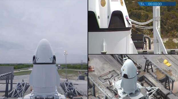
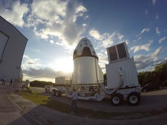
SpaceX has just released new images showing the Dragon crew capsule and trunk section being moved to the launch pad and being positioned atop the launch mount on SLC-40. See above and below. Together the Dragon assembly stands about 20 feet (5 meters) tall.

SpaceX Pad Abort Test vehicle being transported at the Florida launch complex. Credit: SpaceX

A test dummy is seated inside. And SpaceX now says the dummy is not named “Buster” despite an earlier announcement from the company.

“Buster the Dummy already works for a great show you may have heard of called MythBusters. Our dummy prefers to remain anonymous for the time being,” SpaceX said today.

So, only time will tell if that particular mission fact will ever be revealed.

You can watch the Pad Abort Test via a live webcast on NASA TV: http://www.nasa.gov/nasatv

The test window opens at 7 a.m. EDT May 6 and extends until 2:30 p.m. EDT into the afternoon.

The webcast will start about 20 minutes prior to the opening of the window. NASA will also provide periodic updates about the test at their online Commercial Crew Blog.

The current weather forecast predicts a 70% GO for favorable weather conditions during the lengthy test window.

Since the Pad Abort Test is specifically designed to be a development test, in order to learn crucial things about the performance of the escape system, it doesn’t have to be perfect to be valuable.

And delays due to technical issues are a very significant possibility.

“No matter what happens on test day, SpaceX is going to learn a lot,” said Jon Cowart, NASA’s partner manager for SpaceX at a May 1 media briefing at the Kennedy Space Center press site. “One test is worth a thousand good analyses.”

The test is critical for the timely development of the human rated Dragon that NASA is counting on to restore the US capability to launch astronauts from US soil abroad US rockets to the International Space Station (ISS) as early as 2017.

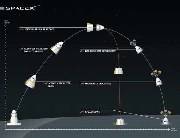
Here’s a graphic illustrating the May 6 SpaceX Pad Abort Test trajectory and sequence of planned events.

Graphic illustrates the SpaceX Pad Abort Test trajectory and sequence of events planned for May 6, 2015 from Cape Canaveral launch complex 40.  Credit: SpaceX
Graphic illustrates the SpaceX Pad Abort Test trajectory and sequence of events planned for May 6, 2015 from Cape Canaveral launch complex 40. Credit: SpaceX

The Crew Dragon will accelerate to nearly 100 mph in barely one second. The test will last less than two minutes and the ship will travel over one mile in the first 20 seconds alone.

The pad abort demonstration will test the ability of a set of eight SuperDraco engines built into the side walls of the crew Dragon to pull the vehicle away from the launch pad in a split second in a simulated emergency to save the astronauts lives in the event of a real emergency.

The SuperDraco engines are located in four jet packs around the base. Each engine produces about 15,000 pounds of thrust pounds of axial thrust, for a combined total thrust of about 120,000 pounds, to carry astronauts to safety.

The eight SuperDraco’s will propel Dragon nearly 100 meters (328 ft) in 2 seconds, and more than half a kilometer (1/3 mi) in just over 5 seconds.

SpaceX likens the test to “an ejection seat for a fighter pilot, but instead of ejecting the pilot out of the spacecraft, the entire spacecraft is “ejected” away from the launch vehicle.”

Here’s a timeline of events from SpaceX:

T-0: The eight SuperDracos ignite simultaneously and reach maximum thrust, propelling the spacecraft off the pad.

T+.5s: After half a second of vertical flight, Crew Dragon pitches toward the ocean and continues its controlled burn. The SuperDraco engines throttle to control the trajectory based on real-time measurements from the vehicle’s sensors.

T+5s: The abort burn is terminated once all propellant is consumed and Dragon coasts for just over 15 seconds to its highest point about 1500 meters (.93 mi) above the launch pad.

T+21s: The trunk is jettisoned and the spacecraft begins a slow rotation with its heat shield pointed toward the ground again.

T+25s: Small parachutes, called drogues, are deployed first during a 4-6 second window following trunk separation.

T+35s: Once the drogue parachutes stabilize the vehicle, three main parachutes deploy and further slow the spacecraft before splashdown.

T+107s: Dragon splashes down in the Atlantic Ocean about 2200 meters (1.4 mi) downrange of the launch pad.

SpaceX Dragon V2 pad abort test flight vehicle. Credit: SpaceX

“This is what SpaceX was basically founded for, human spaceflight,” said Hans Koenigsmann, vice president of Mission Assurance with SpaceX.

“The pad abort is going to show that we’ve developed a revolutionary system for the safety of the astronauts, and this test is going to show how it works. It’s our first big test on the Crew Dragon.”

The pusher abort thrusters would propel the capsule and crew safely away from a failing Falcon 9 booster for a parachute assisted splashdown into the Ocean.

Koenigsmann notes that the SpaceX abort system provides for emergency escape all the way to orbit, unlike any prior escape system such as the conventional launch abort systems (LAS) mounted on top of the capsule.

The next Falcon 9 launch is slated for mid-June carrying the CRS-7 Dragon cargo ship on a resupply mission for NASA to the ISS. On April 14, a flawless Falcon 9 launch boosted the SpaceX CRS-6 Dragon to the ISS.

There was no attempt to soft land the Falcon 9 first stage during the most recent launch on April 27. Due to the heavy weight of the TurkmenÄlem52E/MonacoSat satellite there was not enough residual fuel for a landing attempt on SpaceX’s ocean going barge.

The next landing attempt is set for the CRS-7 mission.

Stay tuned here for Ken’s continuing Earth and planetary science and human spaceflight news.

Ken Kremer

SpaceX Falcon 9 and Dragon blastoff from Space Launch Complex 40 at Cape Canaveral Air Force Station in Florida on April 14, 2015 at 4:10 p.m. EDT  on the CRS-6 mission to the International Space Station. Credit: Ken Kremer/kenkremer.com
SpaceX Falcon 9 and Dragon blastoff from Space Launch Complex 40 at Cape Canaveral Air Force Station in Florida on April 14, 2015 at 4:10 p.m. EDT on the CRS-6 mission to the International Space Station. Credit: Ken Kremer/kenkremer.com

13 MORE Things That Saved Apollo 13, part 10: ‘MacGyvering’ with Everyday Items

Apollo 13 images via NASA. Montage by Judy Schmidt.

To celebrate the 45th anniversary of the Apollo 13 mission, Universe Today is featuring “13 MORE Things That Saved Apollo 13,” discussing different turning points of the mission with NASA engineer Jerry Woodfill.

The night of the explosion on Apollo 13, engineers working in Mission Control and the back-up Mission Evaluation Room (MER) assessed the situation. There were numerous failures in different systems, and finally, instead of just looking at the failures, the engineers had to determine what was actually working on the spacecraft in order to rescue the crew.

A relatively recent term called ‘macgyvering’ was definitely at work during the Apollo 13 mission. Named for the lead character in the television series MacGyver – who usually used duct tape, a Swiss Army knife and anything else he could find to get himself out of sticky or dangerous situations -– macgyvering means solving complex problems by taking something ordinary and using it in an unusual way, but it works perfectly.

The engineers working during the Apollo 13 mission may have been the original “MacGyvers.”

According to NASA engineer Jerry Woodfill, his definition of a good engineer is “one who can take the simplest tool to accomplish the most complex task in the easiest way,” and its corollary, “The greatest engineer is one whose solution is so simple that no one sees his contribution as noteworthy.”

Some of the solutions for Apollo 13’s problems were ingenious. Others were simple, but definitely contributed to the crew’s rescue.

Here’s a look at a few ‘everyday’ items that either the crew were really glad to have on board during the rescue or items that were “macgyvered’ to solve a problem:

The Apollo 13 Lunar Module 'Aquarius' as seen by the crew after the module was jettisoned prior to reentry into Earth's atmosphere. Credit: NASA.
The Apollo 13 Lunar Module ‘Aquarius’ as seen by the crew after the module was jettisoned prior to reentry into Earth’s atmosphere. Credit: NASA.

1. “Jumper cables”

Do you carry a set of jumper cables in your car? Apollo spacecraft didn’t actually have any jump-starting equipment, but a set of heater cables in the Lunar Module were macguyvered to perform as jumper cables.

There were 3 batteries in the Command Module to provide power for reentry, but after the explosion, they had been tapped for a short time to provide power when the fuel cells in the CM shut down. NASA engineers and flight controllers started looking at ways to try and recharge the batteries and came up with using heater cables from the LM in the reverse direction to charge the batteries for the reentry. It was never in the original design to charge the CM batteries from the LM, but the idea was to trickle-charge power from the large lander batteries to the modest capacity entry batteries.

A copy of the invoice sent by Grumman Management to North American Rockwell for charges associated with the Grumman LEM towing Rockwell's CSM back to Earth. Via SpaceRef.
A copy of the invoice sent by Grumman Management to North American Rockwell for charges associated with the Grumman LEM towing Rockwell’s CSM back to Earth. Via SpaceRef.

Two of three batteries were near full 40-amp-hour strength, but the third only had about half that amount. On a normal reentry, they would require 70 to 80 amp hours, but no one wanted to cut it that close on a mission that had so much going against it. So Mission Control told the crew to hook up a cable to the power system of the LM and recharge the weak battery. The process took about 15 hours and drew about 8 amps from the LM.

Famously, the company that built the LM, Grumman Aerospace, sent a mock invoice to the maker of the CM, following the successful return of Apollo 13 for LM’s “towing” service and included was a $5 charge for using the LM for “battery charge.”

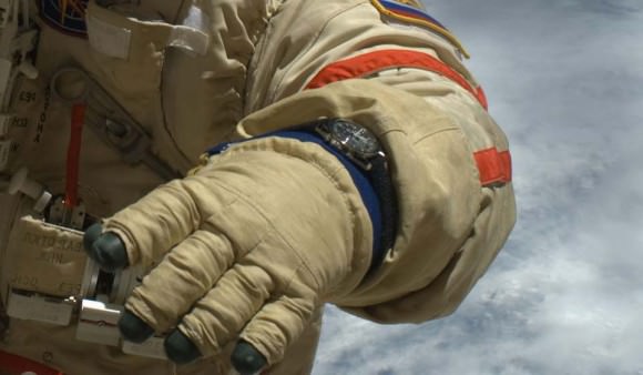
An image of the OMEGA Speedmaster Professional watch worn in space. Image via OMEGA.

2. Watches
NASA supplied each of the Apollo astronauts with a standard issue OMEGA Speedmaster Professional manual-wind wristwatch. The astronauts were expected to wear them during the entire mission, and in fact, the watches were certified to be worn on all extra vehicular activities including the moonwalks. The version the crew used had a long Velcro strap, and with the adjustable strap, the watch could be worn on the outside of the pressure suits.

But more importantly – for Apollo 13 anyway – the watch included a chronograph or stopwatch, using the large third hand on the watch dial. This watch was used to time the manual engine burns to keep Apollo 13 on course and get them safely back to Earth.

However, this wasn’t the first time an Apollo mission used this type of watch in an ‘emergency.’ Buzz Aldrin wrote in his autobiography that an in-cabin timer in the LM had quit working and so during the moonwalk, Neil Armstrong left his Speedmaster inside and it served as a backup timer.

Since the Apollo 13 astronauts used their OMEGA Speedmaster Professionals to time a 14-second mid-course correction, when the company put out a commemorative version of the watch for this 45th anniversary, a small inscription is included on the dial between zero and 14 seconds that asks, “What could you do in 14 seconds?”

In April 1970, the OMEGA Speedmaster was given the “Silver Snoopy Award” from the astronauts for contributing to the rescue of Apollo 13 mission. Fred Haise’s Speedmaster is currently on display at the Penn-Harris-Madison Planetarium in Mishawaka, Indiana.

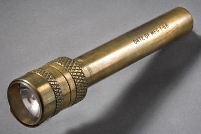
The Model FA-5 Penlight made by ACR Electronics that was used during the Apollo missions. Image via Space Flown Artifacts.

3. Flashlights.

When all the systems were shut down in the CM, the interior became dark and cold. Likewise, most sytems were shut down in the LM as well to save battery power. The crew used flashlights to make their way in the dark and cold cabins.

According to Space Flown Artifacts, NASA used the ACR Model FA-5 Penlight pictured above, a distinctive brass flashlight that were used from Apollo 7 to the early space shuttle missions. The same website quoted a letter dated Apr 19, 1971 from the Apollo 13 crew to ACR Electronics:

“The penlight which you have supplied for the Apollo missions has been very useful and dependable in all missions to date. However, you deserve special praise for the role it played on our mission – Apollo 13.

As you know, due to the explosion, we were forced to ration our electrical power and water. With regard to the former, we never turned on the lights in the spacecraft after the accident. As a result your penlights served as our means of “seeing” to do the job during the many hours of darkness when the sunlight was not coming through the windows. We never wore out even one set during the trip; in fact, they still illuminate today. Their size was also a convenience as it was handy to grip the light between clinched teeth to copy the lengthy procedures that were voiced up from Earth.”

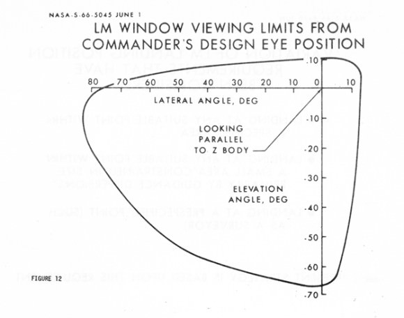
A graphic showing the markings on the windows of the Apollo Lunar Module, which shows T the azimuth and elevation variations of possible viewing limits by the LM pilot. From the NASA report, 'Apollo Lunar Module Landing Strategy.'
A graphic showing the markings on the windows of the Apollo Lunar Module, which shows T the azimuth and elevation variations of possible viewing limits by the LM pilot. From the NASA report, ‘Apollo Lunar Module Landing Strategy.’

4. Window markings on the LM.

The special markings on the LM windows enabled Jim Lovell to hold course by aligning them with the Earth’s terminator. This was crucial to preventing too shallow an entry angle resulting in missing the entry point. According to a NASA report called “Apollo Lunar Module Landing Strategy,” the markings were part of the guidance system, and coupled with the computer system, made it possible for the pilot to “observe the intended landing area by aligning his line-of-sight with the grid marking according to information displayed from the guidance system.”

And so the crew used these markings in a way that wasn’t originally intended, but it made a big impact on the ability of the crew to navigate and fly the ship “by hand.”

John Young's Apollo 16 flown Garland mechanical pencil. Via Space Flown Artifacts.
John Young’s Apollo 16 flown Garland mechanical pencil. Via Space Flown Artifacts.

5. Pencils and pens.
Unlike the space shuttle and space station, there were no printers on board the Apollo spacecraft to print out daily planning reports and updates to the flight plan. The Apollo crews had to do things the ‘old fashioned way’ and used special mechanical pencils and pens that were flight certified to record modified checklist procedures called up to Apollo 13 by Mission Control — as the crew said above, they needed writing instruments to “copy the lengthy procedures that were voiced up from Earth.”

“Without them, crucial onboard operations could not have been performed,” said Woodfill

Again, according to Space Flown Artifacts, for most Apollo missions, the stowage lists show that each astronaut carried a Garland mechanical pencil, and despite the worldwide fame of the Fisher Space Pen it is probably the Garland mechanical pencil that was the most heavily-used writing instrument on the Apollo missions.

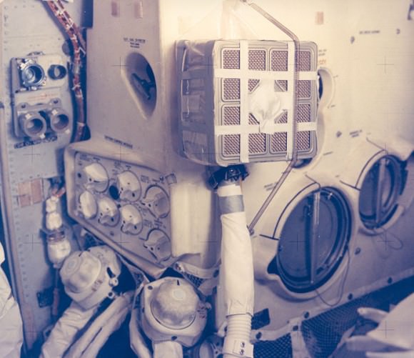
The Apollo 13 fix -- complete with duct tape -- of making a square canister fit into a round hole.  Credit: NASA
The Apollo 13 fix — complete with duct tape — of making a square canister fit into a round hole. Credit: NASA

6. Duct tape, plastic bags, hoses and flight plan covers.

This is the ultimate in macgyvering! As we talked about in the original “13 Things That Saved Apollo 13” series, the crew had to create makeshift CO2 air scrubber out of things they had on the ship. This included duct tape to fashion a Rube Goldberg-like assemblage which the square CO2 filters from the CM to fit the round hole where the LM filters would go – so, fitting a “square peg into a round hole.”

Along with the duct tape were plastic bags that were mostly used for food and other storage, a vacuum-like cleaner/blower and hose that came from the space suits, and cardboard card stock used for the covers of the Apollo reference log manuals. These items all combined to manufacture a simple solution to save the Apollo 13 crew.

Screen shot from Apollo 13 footage showing Jim Lovell with duct tape.

“Without the vacuum like blower called the suit fan and a suitable lengthy hose to route the blower’s airflow to the duct taped filters, rescue might not have happened,” said Woodfill.” “Yes, if not for everyday things on board the ship, perhaps the Apollo 13 crew would not have survived.”

Woodfill often talks to students and he was so taken by how simple things like duct tape saved the crew that he wrote a song ” Tribute to Duct Tape ” which he performs for kids as seen in this video of one of his classes done remotely via Skype:

Previous articles in this series:

Introduction

Part 1: The Failed Oxygen Quantity Sensor

Part 2: Simultaneous Presence of Kranz and Lunney at the Onset of the Rescue

Part 3: Detuning the Saturn V’s 3rd Stage Radio

Part 4: Early Entry into the Lander

Part 5: The CO2 Partial Pressure Sensor

Part 6: The Mysterious Longer-Than-Expected Communications Blackout

Part 7: Isolating the Surge Tank

Part 8: The Indestructible S-Band/Hi-Gain Antenna

Part 9: Avoiding Gimbal Lock

Find all the original “13 Things That Saved Apollo 13″ (published in 2010) at this link.

Spectacular 5th SpaceX Launch in 2015 Sets Record Pace, Clears Path for Critical Flights Ahead

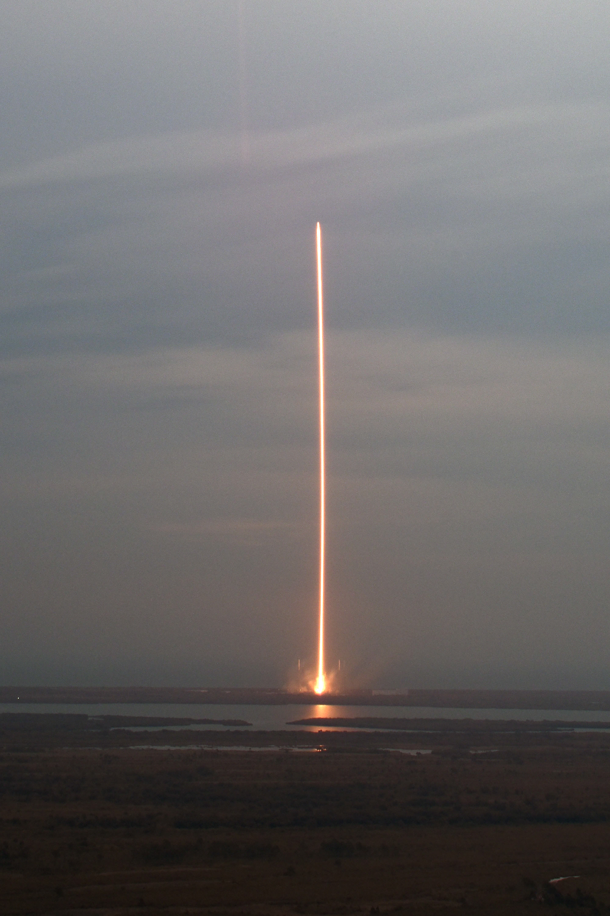
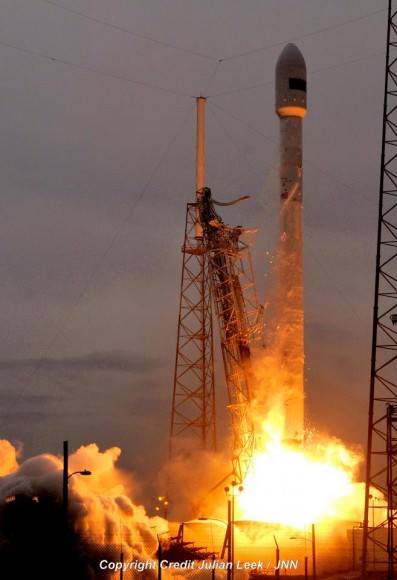
Streak shot taken from VAB roof of dusky blastoff of SpaceX Falcon 9 on April 27, 2015 from Space Launch Complex 40 (SLC-40) at Cape Canaveral Air Force Station, Florida. Credit: SpaceX

SpaceX set a new internal record pace for time between blastoffs of their workhorse Falcon 9 rocket with Monday’s spectacular dusky liftoff of Turkmenistan’s first satellite into heavily overcast skies that has cleared the path ahead for a busy manifest of critical flights starting with a critical pad abort test for NASA just a week from today.

After a 49 minute delay due to grim weather conditions, weather officials finally found a “window in the clouds” that permitted the Falcon 9 to launch on Monday, April 27, 2015 at 7:03pm EDT (2303 GMT).

The launch took place just 13 days after successfully launching the SpaceX Dragon CRS-6 resupply freighter to the International Space Station (ISS) for NASA on April 14.

Overall this launch marked Falcon 9’s fifth launch in four months and second in 13 days, besting SpaceX’s previous turnaround record by one day.

But it was touch and go all afternoon, when two weather rules related to cloudy conditions violated the launch commit criteria and forced a no go from the originally planned 6:14 liftoff time.

The situation was not at all promising when the weather officer announced “NO GO” during the prelaunch poll that resulted in a recycle to the T minus 20 minute mark with seemingly little prospect of a launch. Then all of a sudden, conditions improved and the count was resumed and “wet off without a hitch” said SpaceX.

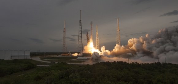
On April 27, 2015 at 7:03 p.m. EDT, Falcon 9 lifted off from SpaceX’s Launch Complex 40 at Cape Canaveral Air Force Station carrying the TurkmenÄlem52E/MonacoSat satellite. Credit: SpaceX

The 224 foot tall SpaceX Falcon 9 launched on a commercial mission for Thales Alenia Space carrying the first ever communications satellite for the nation of Turkmenistan.

The TurkmenÄlem52E/MonacoSat satellite was built by Thales Alenia Space.

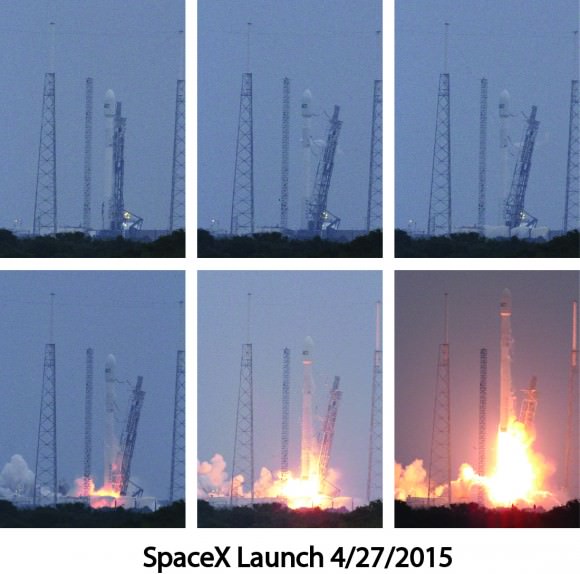
Launch sequence showing blastoff of SpaceX Falcon 9 on April 27, 2015 from Space Launch Complex 40 (SLC-40) at Cape Canaveral Air Force Station, Florida.  Credit: Chuck and Carol Higgins
Launch sequence showing blastoff of SpaceX Falcon 9 on April 27, 2015 from Space Launch Complex 40 (SLC-40) at Cape Canaveral Air Force Station, Florida. Credit: Chuck and Carol Higgins

The 14 story Falcon 9 first stage is powered by 9 Merlin 1D engines that generate about 1.3 million pounds of thrust.

The Falcon 9’s first and second stages separated three minutes after launch. The second stage fired for six minutes for its first burn to reach the initial parking orbit. It then reignited twenty-six minutes into flight, to completed a one-minute burn.

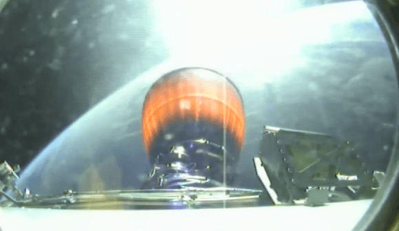
Rocket cameras capture In flight view of Falcon 9 second stage engine firing back dropped by Earth. Credit: SpaceX

The launch delivered the 10,375-pound (4500 kg) TurkmenÄlem52E/MonacoSat satellite to a geosynchronous transfer orbit. The satellite was deployed as planned approximately 32 minutes after liftoff.

Launches are never easy, as exemplified by a post launch tweet from SpaceX CEO Elon Musk after the satellite was deployed from the second stage.

‘Rocket launch good, satellite in geo transfer orbit. Still so damn intense. Looking fwd to it feeling normal one day,” tweeted Musk.

Despite the launch of Turkmenistan’s first communications satellite, the country is conducting a war on satellite dishes to receive the signals according to Human Rights Watch.

“Authorities in Turkmenistan are forcing residents to dismantle privately owned satellite dishes,” Human Rights Watch said in a statement on April 24. “A move that unjustifiably interferes with the right to receive and impart information and ideas, this serves to further isolate people in Turkmenistan, one of the most closed and repressive countries in the world, from independent sources of news and information.”

First-ever Turkmenistan satellite launches aboard SpaceX's Falcon rocket on April 27, 2015 from Cape Canaveral Air Force Station, Florida. Credit: Julian Leek
First-ever Turkmenistan satellite launches aboard SpaceX’s Falcon rocket on April 27, 2015 from Cape Canaveral Air Force Station, Florida. Credit: Julian Leek

Just 1 week from today on May 5, SpaceX plans a pad abort test for NASA that is critical for the timely development of the human rated Dragon that NASA is counting on to restore the US capability to launch astronauts from US soil to the space station.

The next Falcon 9 launch is slated for mid-June carrying the CRS-7 Dragon cargo ship on a NASA mission to the ISS.

There was no attempt to soft land the Falcon 9 first stage during the April 27 launch. Due to the heavy weight of the TurkmenÄlem52E/MonacoSat satellite there was not enough residual fuel for a landing attempt on SpaceX’s ocean going barge.

The next landing attempt is set for the CRS-7 mission.

Stay tuned here for Ken’s continuing Earth and planetary science and human spaceflight news.

Ken Kremer

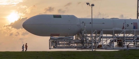
Falcon 9 rocket rolls out to the pad prior to April 27, 2015 launch. Credit: SpaceX

SpaceX Picks Up Launch Pace; Sets April 27 Commercial Launch and May 5 Crew Dragon Pad Abort Test

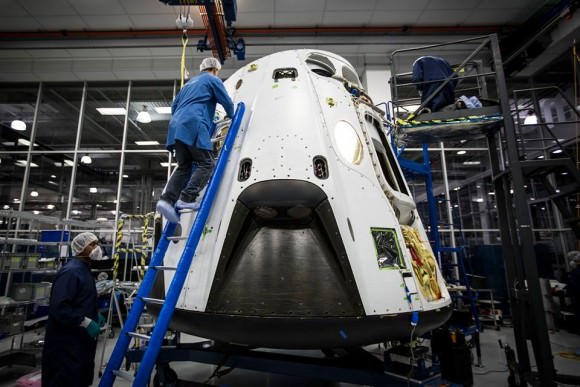
SpaceX Dragon V2 pad abort test flight vehicle. Credit: SpaceX

SpaceX Dragon V2 test flight vehicle set for May 5, 2015 pad abort test. Credit: SpaceX
See below SpaceX live launch webcast link[/caption]

As promised, SpaceX is picking up its launch pace in 2015 with a pair of liftoffs from the Florida space coast slated for the next week and a half. They follow closely on the heels of a quartet of successful blastoffs from Cape Canaveral, already accomplished since January.

If all goes well, a commercial satellite launch and a human spaceflight related pad abort test launch for NASA are scheduled for April 27 and May 5 respectively.

Mondays launch of a communications satellite for Thales Alenia Space takes place just 13 days after SpaceX successfully launching the Dragon CRS-6 resupply freighter to the International Space Station (ISS) for NASA on April 14.

The 13 day turnaround time will mark a new launch cadence record for SpaceX if the weather and rocket cooperate, eclipsing the 14 day turnaround record set last September.

SpaceX Falcon 9 and Dragon blastoff from Space Launch Complex 40 at Cape Canaveral Air Force Station in Florida on April 14, 2015 at 4:10 p.m. EDT  on the CRS-6 mission to the International Space Station. Credit: Ken Kremer/kenkremer.com
SpaceX Falcon 9 and Dragon blastoff from Space Launch Complex 40 at Cape Canaveral Air Force Station in Florida on April 14, 2015 at 4:10 p.m. EDT on the CRS-6 mission to the International Space Station. Credit: Ken Kremer/kenkremer.com

The 224 foot tall SpaceX Falcon 9 rocket is scheduled to launch at approximately 6:14 p.m. EDT (2214 GMT) on April 27 from Space Launch Complex 40 (SLC-40) at Cape Canaveral Air Force Station, Florida. It will deliver the TurkmenÄlem52E/MonacoSat satellite to a geosynchronous transfer orbit.

This first satellite ever for Turkmenistan will be deployed approximately 32 minutes after liftoff of the fifth Falcon 9 rocket this year.

The outlook is currently 60 percent GO for favorable weather conditions at launch time.

You can watch the launch live via a SpaceX webcast that begins about 20 minutes before launch at: spacex.com/webcast

The May 5 pad abort test for NASA is critical for the timely development of the human rated Dragon that NASA is counting on to restore the US capability to launch astronauts from US soil to the space station.

The test will simulate an emergency abort from a test stand and will also take place from the Cape’s Space Launch Complex 40 in Florida.

SpaceX has a four hour launch window in which to conduct the test. The test window opens at 9:30 a.m. EDT (1330 GMT) on May 5. There is a backup opportunity on May 6.

The pad abort demonstration will test the ability of a set of eight SuperDraco engines built into the side walls of the crew Dragon to pull the vehicle away from the launch pad in a split second in a simulated emergency.

First look at the SpaceX Crew Dragon’s pad abort vehicle set for flight test in March 2014.  Credit: SpaceX.
First look at the SpaceX Crew Dragon’s pad abort vehicle set for flight test in March 2014. Credit: SpaceX.

The purpose is to test the ability of the abort system to save astronauts lives in the event of a real emergency.

The SuperDraco engines are located in four jet packs around the base. Each enigne can produce up to 120,000 pounds of axial thrust to carry astronauts to safety, according to a SpaceX description.

Here is a SpaceX video of SuperDraco’s being hot fire tested in Texas.

Video caption: Full functionality of Crew Dragon’s SuperDraco jetpacks demonstrated with hotfire test in McGregor, TX. Credit: SpaceX

The pad abort test is being done under SpaceX’s Commercial Crew Integrated Capability (CCiCap) agreement with NASA.

The initial pad abort test will test the ability of the full-size Dragon to safely push away and escape in case of a failure of its Falcon 9 booster rocket in the moments around launch, right at the launch pad.

“The purpose of the pad abort test is to demonstrate Dragon has enough total impulse (thrust) to safely abort,” SpaceX spokeswoman Emily Shanklin informed me.

For that test, Dragon will use its pusher escape abort thrusters to lift the Dragon safely away from the failing rocket.

The vehicle will be positioned on a structural facsimile of the Dragon trunk in which the actual Falcon 9/Dragon interfaces will be represented by mockups. The test will not include an actual Falcon 9 booster.

A second Dragon flight test follow later in the year. It involves simulating an in flight emergency abort scenario during ascent at high altitude at maximum aerodynamic pressure at about T plus 1 minute, to save astronauts lives. The pusher abort thrusters would propel the capsule and crew safely away from a failing Falcon 9 booster for a parachute assisted landing into the Atlantic Ocean.

The SpaceX Dragon V2 and Boeing CST-100 vehicles were selected by NASA last fall for further funding under the auspices of the agency’s Commercial Crew Program (CCP), as the worlds privately developed spaceships to ferry astronauts back and forth to the International Space Station (ISS).

Both SpaceX and Boeing plan to launch the first manned test flights to the ISS with their respective transports in 2017.

During the Sept. 16, 2014 news briefing at the Kennedy Space Center, NASA Administrator Charles Bolden announced that contracts worth a total of $6.8 Billion were awarded to SpaceX to build the manned Dragon V2 and to Boeing to build the manned CST-100.

There will be no attempt to soft land the Falcon 9 first stage during the April 27 launch. The next landing attempt is set for mid-June.

Up close view of the SpaceX Falcon 9 rocket landing legs prior to launch on April 14, 2015 on the CRS-6 mission to the International Space Station. Credit: Ken Kremer/kenkremer.com

Stay tuned here for Ken’s continuing Earth and planetary science and human spaceflight news.
Ken Kremer

13 MORE Things That Saved Apollo 13, part 9: Avoiding Gimbal Lock

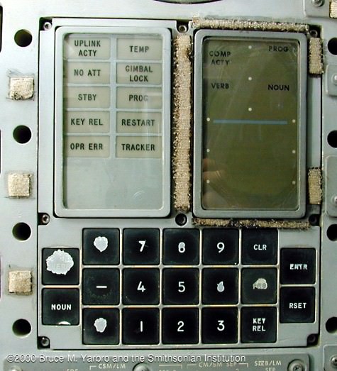
The Display & Keyboard (DSKY) mounted in the Main Display Console of the Apollo 13 spacecraft, Odyssey. Note the gimbal lock display in the second row. Credit: NASA/The Apollo Flight Journal

It was an unlikely case, having an Apollo command ship disabled thousands of miles from Earth. But during the Apollo 9 mission, the crew had actually conducted a test of firing the Lunar Module’s engines while it was docked to the Command Module. It turned out to be fortuitous to have considered such a situation, but Apollo 9 didn’t have to perform the type of maneuvering under the myriad of conditions Apollo 13 faced.

Steering was among the crucial threats for Jim Lovell and his crew. Without the command ship’s thrusters to steer, only the lander’s were available, and flying the crippled Apollo 13 spacecraft stack and keeping it on the right trajectory was a huge challenge.

During a normal mission, the ship’s computers allowed for much of the navigation, but the Apollo 13 crew had to fly “by hand.” The Command Module was shut down, and the LM’s limited battery power required the shutting down most of its systems, so even backup propulsion and navigation functions were unavailable. Lovell had to struggle to bring the unwieldy two-vehicle craft under control.

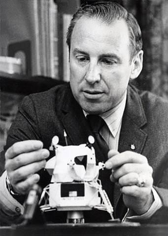
Apollo 13 commander Lovell with a model Lunar module. Image credit: NASA
The lander’s steering was fashioned to handle only its mass and center of mass location. Now it had to steer the entire assemblage, which included the dead mass of the Command and Service Module as well as the lander. Then there was oxygen venting from the damaged tanks in the SM. This all contributed to putting the stack through contortions of pitch, roll, and yaw.

In his seminal book, “A Man on the Moon,” author Andrew Chaikin succinctly captured the scene:

Even now, oxygen spewed from Odyssey’s side like blood from a harpooned whale. The escaping gas acted like a small rocket, fighting Lovell’s efforts to stabilize the joined craft – which the astronauts called “the stack” – with Aquarius’s thrusters. Lovell soon found that trying to control the stack from the lander was strange and awkward, like steering a loaded wheelbarrow down the street with a long broom handle. When he nudged the hand controller the joined craft wobbled unpredictably. It was, Lovell would say later, like learning to fly all over again. And he had to learn fast, because if he let the spacecraft drift uncontrolled, there was a danger that one of Aquarius’s gyros would be immobilized – a condition called gimbal lock that would ruin the alignment of the navigation platform. With no way of sighting in the stars, there would be no hope of realigning it….
“I can’t take that doggone roll out, “Lovell said. Throughout the next 2 hours Lovell wrestled with his unwieldy craft, as the time for the free-return maneuver approached. He wondered if Aquarius would be able to point them toward home, and whether it would last long enough to get them there. Lovell and his crew had become the first astronauts to face the very real possibility of dying in space.

From “A Man on the Moon,” chapter 7, “The Crown of an Astronaut’s Career”
by Andrew Chaikin
Used by permission
.

One of the items discussed in the original “13 Things That Saved Apollo 13” was how well suited rookie Apollo crewman Jack Swigert was to the Apollo 13 mission, as he was said to have basically ‘wrote the book’ on Command Module malfunctions. Likewise, says NASA engineer Jerry Woodfill, was Commander Jim Lovell’s ability as Apollo 13’s helmsman.

“Tales are often shared about Lovell’s skills as a naval aviator,” said Woodfill, “making aircraft carrier deck landings in the dark with a malfunctioning display, or in storm-tossed seas.”

Being able to judge aircraft descent rates and attitude with respect to a wave-tossed carrier deck was a challenge. Woodfill said this ideally trained Lovell for avoiding gimbal-lock on Apollo 13.

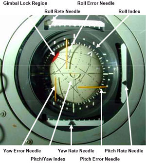
An annotated image of the Apollo Flight Director Attitude Indicator, commonly called the navigation 8-ball. Via Kerbal Space Program.

“Gimbal-lock meant the guidance system could no longer trust its computer,” explained Woodfill. “The guidance system’s orthogonal gyroscopes (gyros) judged the degree of pitch, roll, and yaw. Gimbal-lock exceeded the system’s ability to gauge position. Such an instance could be compared to an automobile’s tires slipping on an icy road. Steering becomes almost useless in such an event.”

Historian and journalist Amy Shira Teitel recently posted this video in regards to gimbal lock and Apollo 13:

Then, later came a second dire “steering” challenge to Lovell and his crew. Apollo ships required a rotating maneuver about their longest axis known as Passive Thermal Control (PTC), nicknamed the rotisserie, to protect one part of the spacecraft from continually being baked by the Sun. Normally, this was done by the CM’s computer, and the LM’s computer didn’t have the software to perform this operation. Lovell had to maneuver the unwieldy ship by hand nearly every hour to perform the “slow motion barbeque spin” as Chaikin called it. Without the CM’s orientation control thrusters and having the center of gravity extremely off-center with respect to the lander’s control system, it made the situation problematical.

“Lovell seemed to have the ability to quickly adapt to difficult situations,” said Woodfill, “and the knack of quickly coming up with solutions to problems.”

But that’s part of the makeup of being a test pilot and what distinguished the men who were chosen to be astronauts in the Apollo program.

“As great a pilot as Jim Lovell was, I think any of the Apollo commanders could have handled that situation from a piloting point of view,” Chaikin told Universe Today via phone. “One benefit that Lovell brought to the situation was his calm, composed personality—a real asset during that entire ordeal.”

As Chaikin quoted original Apollo 13 crew member Ken Mattingly in “A Man on the Moon,” if Apollo 13 had to happen to any spacecraft commander, there wasn’t anyone who could have handled it better than Jim Lovell.

Nancy Atkinson with Jim Lovell in 2010 at the Abraham Lincoln Presidential Museum.

Here’s an additional, more technical description of gimbal lock:

Previous articles in this series:

Introduction

Part 1: The Failed Oxygen Quantity Sensor

Part 2: Simultaneous Presence of Kranz and Lunney at the Onset of the Rescue

Part 3: Detuning the Saturn V’s 3rd Stage Radio

Part 4: Early Entry into the Lander

Part 5: The CO2 Partial Pressure Sensor

Part 6: The Mysterious Longer-Than-Expected Communications Blackout

Part 7: Isolating the Surge Tank

Part 8: The Indestructible S-Band/Hi-Gain Antenna

Find all the original “13 Things That Saved Apollo 13″ (published in 2010) at this link.

Apollo 13 images via NASA. Montage by Judy Schmidt.

13 MORE Things That Saved Apollo 13, part 8: The Indestructible S-Band/Hi-Gain Antenna

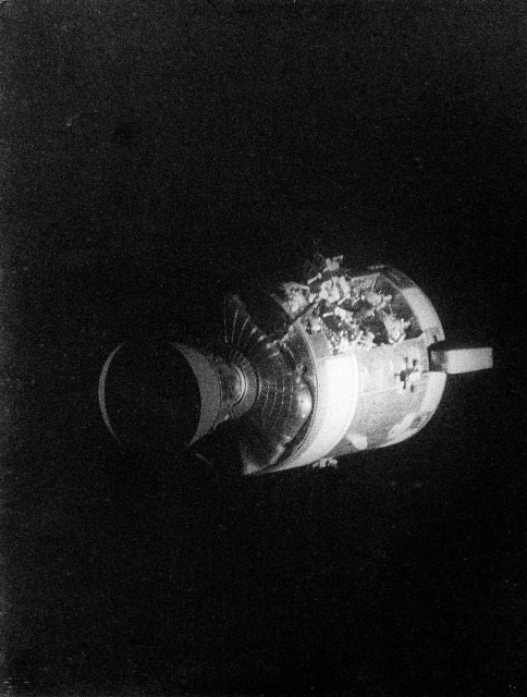
This view of the severely damaged Apollo 13 Service Module (SM) was photographed from the Lunar Module/Command Module (LM/CM) following SM jettisoning. As seen here, an entire panel on the SM was blown away by the apparent explosion of oxygen tank number two located in Sector 4 of the SM. Credit: NASA.

The explosion of a liquid oxygen tank in Apollo 13’s Service Module violently propelled debris and a 13-foot (4 meter) outer panel of the SM out into space.

Later, the crew saw the damage when they jettisoned the SM prior to reentering Earth’s atmosphere. Commander Jim Lovell described the scene:

“There’s one whole side of the spacecraft missing!” Lovell radioed to Mission Control. “Right by the high-gain antenna, the whole panel is blown out, almost from the base to the engine.”

The panel was likely blasted outward and rearward, toward the deep space S-Band radio antenna. The antenna was attached to the outer edge of the module’s rear base via a meter-long strut, and was used for both telemetry and voice communications.

NASA engineer Jerry Woodfill feels this hi-gain antenna was surely struck by the panel and/or schrapnel ejected by the oxygen tank explosion.

“That deep space radio communication was maintained during and after the explosion was almost miraculous,” Woodfill said. “Such a blow should have destroyed that hi-gain antenna. Those of us who watched the telemetry display monitors saw only a momentary flickering of the telemetry, but after a few flickers we continued to receive data.”

Woodfill said it was as though a boxer had taken a devastating punch and continued to stand unfazed.

This video of the severely damaged Apollo 13 service module was taken by the crew after it was jettisoned.

If instead, the antenna had been destroyed, the loss of data would have resulted in an impaired ability to analyze the situation and communicate with the crew.

The moments following the explosion are seared into Woodfill’s memory. On the night of April 13, 1970, 27-year-old Woodfill sat at his console in the Mission Evaluation Room (MER) in Building 45 at Johnson Space Center — next door to Mission Control in Building 30 — monitoring the caution and warning system.

Jerry Woodfill working in the Apollo Mission Evaluation Room.  Credit:  Jerry Woodfill.
Jerry Woodfill working in the Apollo Mission Evaluation Room. Credit: Jerry Woodfill.
“Because I was watching the command ship’s telemetry on a monitor at the moment of the explosion, both the words heard in my headset, “Houston, we’ve had a problem” and the scene I saw of the video monitor have not been forgotten” Woodfill said. “Seconds before I heard the audio of Jack Swigert’s call, I watched the video screen flicker several times.

To this day, Woodfill said he cannot understand how it continued to function following the explosion.

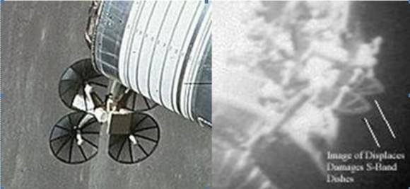
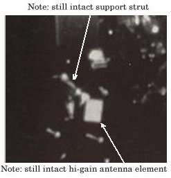
“As an engineer, I have studied the basics of simple machines,” he said. “The concept of the lever arm dictates that when an explosive blow strikes a structure atop an arm, the arm must bend back about its attachment to the supporting structure. In this case, that structure was the command ship’s supply module, the Service Module. Later photos by the crew (below) showed the antenna intact and the conical reflector dishes present with their center probes intact. In my mind, the entire assembly simply should have been severed altogether.”

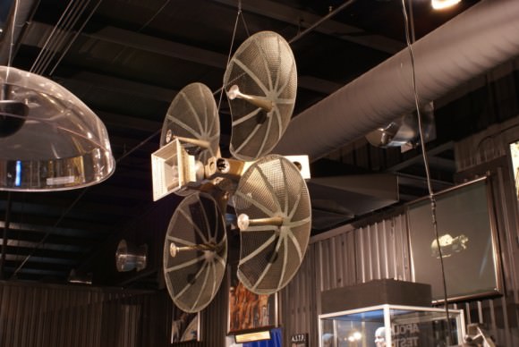
An Apollo high gain antenna, on display at the Stafford Air & Space Center, Weatherford, Oklahoma.

The Unified S-band (USB) system was a tracking and communication system that combined television, telemetry, command, tracking and ranging into a single system. The high-gain antenna consisted of an 11-inch-diagonal wide-beam horn flanked by an array of four 31-inch-diameter parabolic reflectors. Its multifunctional system simplified operations, and its construction saved on weight.

And obviously, it was very durable.

Woodfill reiterated how important it was that the antenna survived the explosion.

“Later on it wasn’t needed, as the crew used the Lunar Module communication system,” said Woodfill, “but having that initial continuous communication was one of the things that was very important.”

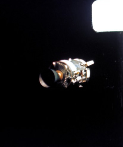
This color view of the severely damaged Apollo 13 Service Module (SM) was photographed with a motion-picture camera from the Lunar Module/Command Module following SM jettison. Credit: NASA.

And later those in Mission Control and the MER were be able to go back and look at the data that had been transmitted to Earth during that very crucial period of the mission, to help understand what had actually occurred.

“It was critical to have that data in those first moments of the explosion to analyze what had happened,” Woodfill said. “Uninterrupted communication was essential to investigating the status of the vehicle. While it may be true that the backup omni-antenna might have provided temporary communication, based on my analysis, the omni-antenna would not have served as ably during the time of greatest initial peril. In fact, to configure its use with the NASA world-wide tracking network would have caused an unfortunate delay.”

Here are some zoomed-in photos taken by the crew of Apollo 13 after the explosion of the S-Band/hi-gain antenna, and Woodfill has noted the parts of the antenna. They show the explosion failed to sever the hi-gain antenna mast and the conical dish receivers as well as the rectangular antenna, and the center probes of the conical dishes appear intact. Considering the force of the explosion, this is remarkable.

At left, a view of the Service Module and the S-Band antenna during a previous Apollo mission. At right is a zoomed in look at the damaged SM and the unfazed S-Band antenna on Apollo 13, taken during SM jettison. Credit: NASA/Jerry Woodfill.
An annotated closeup of the S-Band/Hi Gain antenna on Apollo 13 after the explosion. Credit: NASA/Jerry Woodfill.
Apollo 13 images via NASA. Montage by Judy Schmidt.

Previous articles in this series:

Introduction

Part 1: The Failed Oxygen Quantity Sensor

Part 2: Simultaneous Presence of Kranz and Lunney at the Onset of the Rescue

Part 3: Detuning the Saturn V’s 3rd Stage Radio

Part 4: Early Entry into the Lander

Part 5: The CO2 Partial Pressure Sensor

Part 6: The Mysterious Longer-Than-Expected Communications Blackout

Part 7: Isolating the Surge Tank

Find all the original “13 Things That Saved Apollo 13″ (published in 2010) at this link.